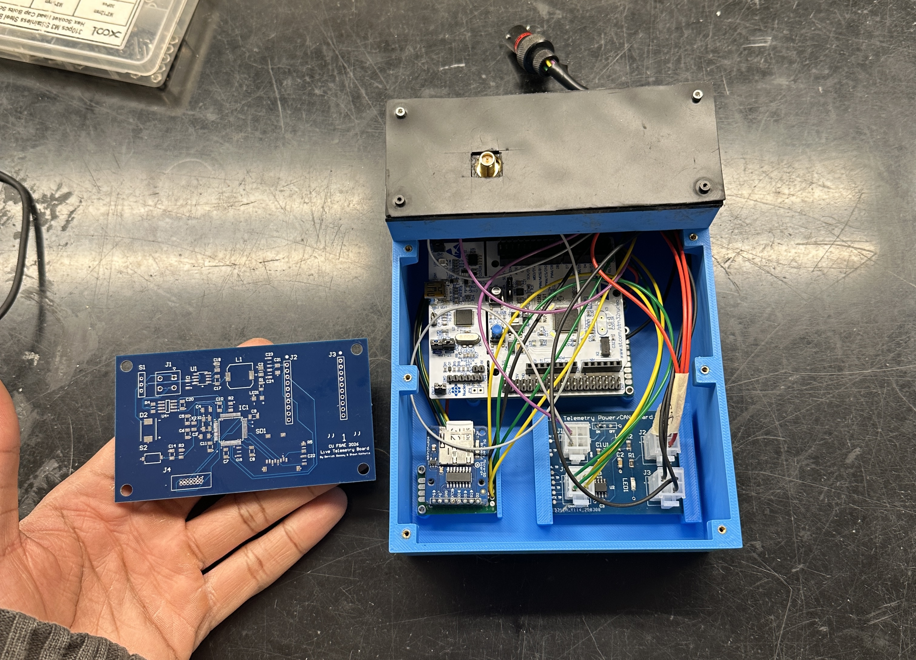
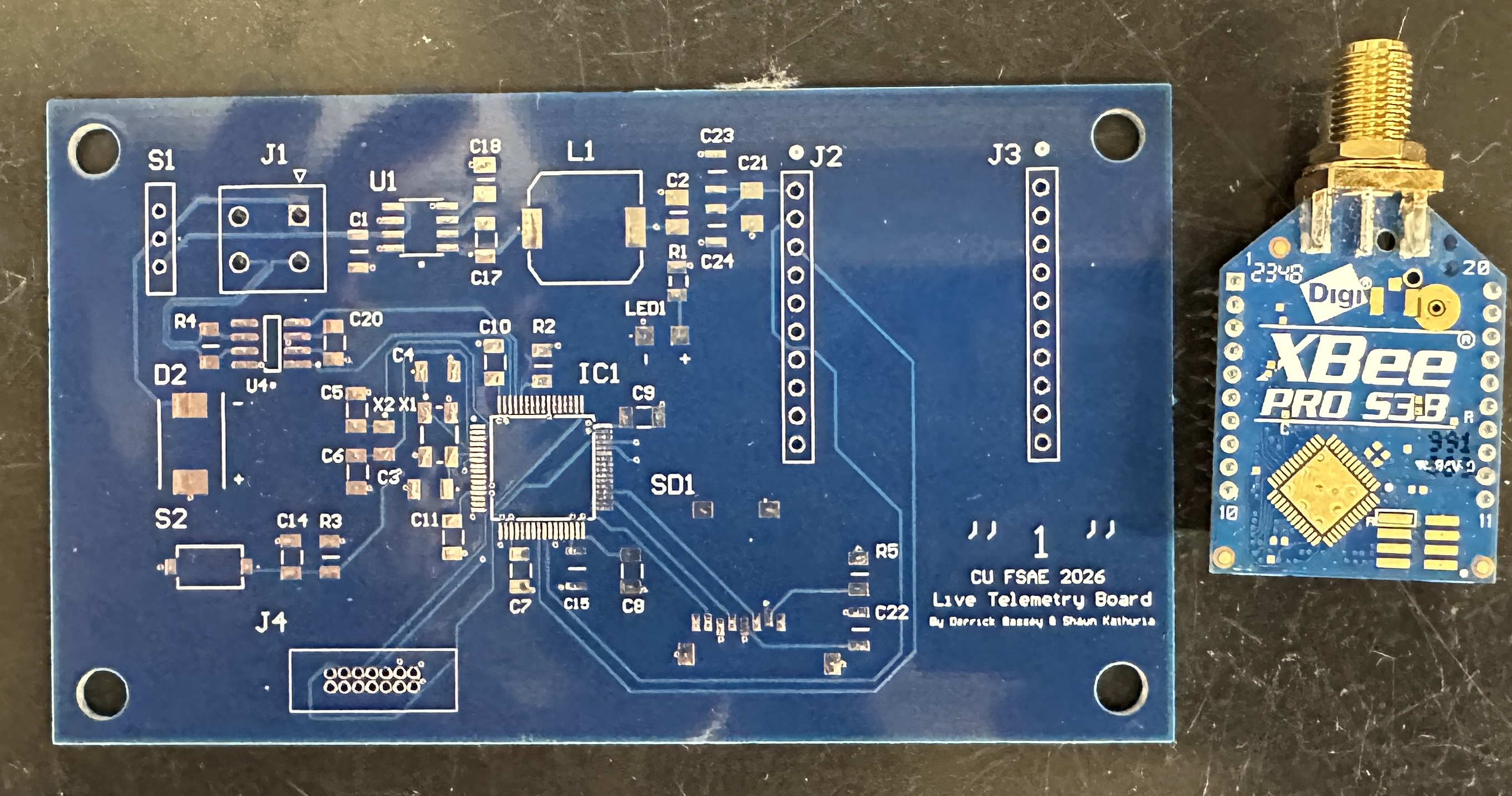
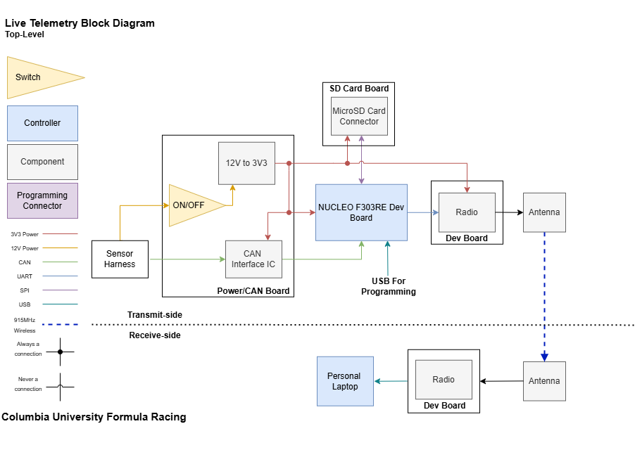
The Telemetry PCB is an application specific PCB that serves as the central hub for the vehicle’s data acquisition and wireless telemetry. It replaces a previous architecture built from multiple development boards by integrating CAN interfacing, wireless communication, SD card data logging, and onboard power regulation onto a single PCB.
The board interfaces with the vehicle’s CAN bus, processes telemetry data using an STM32 microcontroller, and transmits real-time data wirelessly through an XBee radio module. It enables live off car monitoring of key vehicle performance metrics such as wheel speeds, torque signals, and vehicle acceleration.
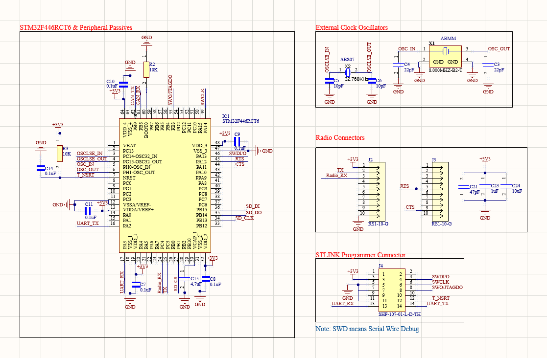
The schematic was built around an STM32F446RCT6 microcontroller responsible for receiving CAN data, packaging telemetry packets, logging data to an SD card, and transmitting packets through the radio module. The board interfaces with the vehicle network through an SN65HVD230 CAN transceiver, allowing telemetry messages from the vehicle CAN bus to be decoded and forwarded to the telemetry system.
Power for the board is derived from the vehicle 24 V supply, which is stepped down to 3.3 V using an LMR36503 buck regulator. Local decoupling capacitors were placed throughout the design to stabilize the supply rails and reduce switching noise.
An XBee radio interface provides wireless communication with the ground station dashboard, while a microSD card interface allows telemetry data to be logged locally through the SPI interface for redundancy. External crystal oscillators and an SWD programming header were also included to support a 10MHz clock and easy debugging during firmware development.
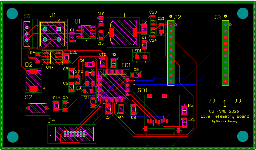
The board was implemented as a 4-layer PCB to improve signal integrity and power distribution. Dedicated internal layers were used for solid ground and power planes, providing low-impedance return paths and reducing switching noise from the buck converter and digital circuitry.
High-speed signals such as SPI and CAN were routed with minimal vias and short trace lengths to reduce impedance discontinuities. Decoupling capacitors were placed directly adjacent to the corresponding power pins of the microcontroller and other ICs to minimize loop inductance and ensure stable supply rails.
Additional placement constraints were applied for EMI and power integrity. The radio module was positioned near the board edge and isolated from noisy power components, while the switching regulator and inductor were placed away from sensitive digital and RF circuitry to reduce conducted and radiated noise coupling.

The final telemetry PCB successfully integrated the functionality of several development boards into a single compact design. The board was able to receive CAN data from the vehicle, process and transmit telemetry packets through the radio link, and simultaneously log data to the onboard SD card.
This consolidation reduced wiring complexity and improved system reliability while maintaining all telemetry capabilities required for the vehicle dashboard.